
ZCO3 & ZCO3-SH Main Signalling Cables (AC Electrified High Speed Lines)
Application
The cables are designed for connection between traffi c control centers and equipment shelters along the trackside. The cables are specially designed to give good induction protection (R.F=0.21 at inductive voltage 100V/km) and are suitable for installation in high speed railway lines electrifi ed at 25KV ac.
Standards
- SNCF CT 445
- NF F 55-698
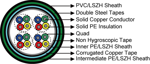
Construction
- Conductors: Solid annealed copper, 1.0 mm² nominal cross section area.
- Insulation: Solid polyethylene.
- Cabling Element: Four conductors are twisted to form a quad.
- Stranding: Quads are helically stranded to get the cable core.
- Core Wrapping: Plastic tape(s) with overlapping.
- Inner Sheath: Low density polyethylene. LSZH FR option can be offered upon request to NF C 32 070.2.2 (C1).
- Electrostatic Shield: Corrugated copper tape.
- Intermediate Sheath: Low density polyethylene. LSZH FR option can be offered upon request to NF C 32 070.2.2 (C1).
- Electromagnetic Shield: Two helically applied steel tapes (0.5mm).
- Outer Sheath: PE/PVC compound. LSZH FR option can be offered upon request to NF C 32 070.2.2 (C1).
- Remarks: ZCO3: PE/PVC Sheath; ZCO3-SH: LSZH Sheath.
Electrical Characteristics at 20℃
| Nominal Conductor Diameter | mm | 1.13 |
| Nominal Cross Section Area | mm² | 1.0 |
| Maximum Conductor Resistance (DC) | Ω/km | 18.1 |
| Minimum Insulation Resistance @500 V DC (3mins) | MΩ.km | 5000 |
| Maximum Mutual Capacitance @1000Hz (AC) | nF/km | 40 |
| Maximum Capacitance Unbalance @800Hz | pF/500m | 400 |
| Dielectric Strength, conductor to conductor (DC voltage 3mins) | V | 4500 |
| Operating Voltage AC/DC | V | 450/750 |
Reduction Factor
| Inductive voltage(V/km) | 50 | 70 | 100 | 370 | 400 | 470 |
| Reduction factor @50Hz | 0.42 | 0.30 | 0.20 | 0.16 | 0.18 | 0.31 |
Mechanical and Thermal Properties
- Minimum Bending Radius: 8×OD (static); 16×OD (dynamic)
- Temperature Range: -40℃ to +70℃ (during operation); -20℃ to +50℃ (during installation)
Dimensions and Weight
| Cable Code | No. of Quads |
Nominal Sheath Thickness mm |
Nominal Overall Diameter mm |
Nominal Weight kg/km |
||
| Inner | Interm. | Outer | ||||
| 1.13mm Conductor, 2.33 Insulated Wire | ||||||
| RS/ZCO3-2Y2Y(K)2YB2Y-2Q1S | 2 | 0.8 | 1.0 | 1.6 | 27.0 | 1295 |
| RS/ZCO3-2Y2Y(K)2YB2Y-4Q1S | 4 | 0.8 | 1.0 | 1.6 | 29.5 | 1490 |